8-bit Arithmetic Logic Unit
Problem Statement: Design and simulate a 8-bit ALU.
Introduction to ALU
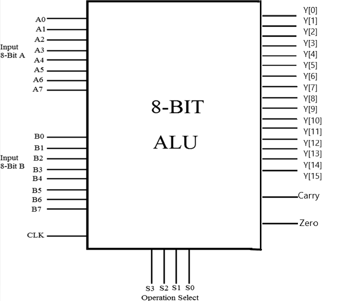
Implementation Table of 8-bit ALU
| Arithmetic Operations | Logical Operations |
|---|---|
| Addition | Bitwise AND & NAND |
| Subtraction | Bitwise OR & NOR |
| Multiplication | Bitwise NOR & XNOR |
| Division | Shift Right & Shift Left |
| Increment | Rotate Right & Rotate Left |
| Decrement |
| s | operation | a | b | y | carry | zero |
|---|---|---|---|---|---|---|
| 0000 | Addition | 11101110 | 11101110 | 00000000 11011100 | 1 | 0 |
| 0001 | Subtraction | 11101110 | 11101110 | 00000000 00000000 | 0 | 1 |
| 0010 | Increment | 11101110 | 11101110 | 00000000 11101111 | 0 | 0 |
| 0011 | Decrement | 11101110 | 11101110 | 00000000 11101101 | 0 | 0 |
| 0100 | Multiplication | 11101110 | 11101110 | 11011101 01000100 | 0 | 0 |
| 0101 | Division | 11101110 | 11101110 | 00000000 00000001 | 0 | 0 |
| 0110 | Bitwise AND | 11101110 | 11101110 | 00000000 11101110 | 0 | 0 |
| 0111 | Bitwise OR | 11101110 | 11101110 | 00000000 11101110 | 0 | 0 |
| 1000 | Bitwise XOR | 11101110 | 11101110 | 00000000 00000000 | 0 | 1 |
| 1001 | Bitwise NAND | 11101110 | 11101110 | 00000000 00010001 | 0 | 0 |
| 1010 | Bitwise NOR | 11101110 | 11101110 | 00000000 00010001 | 0 | 0 |
| 1011 | Bitwise XNOR | 11101110 | 11101110 | 00000000 11111111 | 0 | 0 |
| 1100 | Shift Left | 11101110 | 11101110 | 00000000 11011100 | 1 | 0 |
| 1101 | Shift Right | 11101110 | 11101110 | 00000000 01110111 | 0 | 0 |
| 1110 | Rotate Right | 11101110 | 11101110 | 00000000 01110111 | 0 | 0 |
| 1111 | Rotate Left | 11101110 | 11101110 | 00000000 11011101 | 0 | 0 |
Implementation of 8-bit ALU
To implement 8-bit ALU design, follow these steps.
-
Create a new Verilog file and start writing code for 8-bit ALU as given below and save the file. Keep the file name as ALU.
-
We will use testbench to verify the output of this design. Create a new Verilog file and type the testbench code provided below and Save the file with the same name as the module name.
-
Compile the code and check for any syntax errors using the below command.
iverilog ALU.v tb_ALU.v -o ALU -
If there are no errors, use the below command for running the simulation.
vvp ALUYou will see the values of signals being monitored across each clocktick.
-
If all looks well, use the below command for viewing the waveform. Add the signals from
tb_ALUdesign to the window to view the simulation output as shown in below image.gtkwave alu.vcd